Mechatronics
A major U-turn from more traditional Formula 1 racecars…
Through UPenn’s Mechatronics course (MEAM-510), I worked with two classmates to design, build, encode, test, and compete with a versatile and fast electromechanical autonomous car. Further, the robot (and its networking supplementals) served to perform six main functions (as outlined in the “Task Completion via Hardware & Software” section below) pertaining to wireless networking, manual control, and self-driving capabilities. To that end, we attached several electronics, including various sensors (ultrasonic distance, phototransistor IR, and Vive location), two Adafruit DC Gearbox “TT” motors, my Anker Powercore 1300 supplying power, and for computation, a single ESP32 MCU. We used an off-board laptop to implement all logic in C++, and display a UDP-facilitated HTML webpage streaming real-time car data and accepting user instructions.
Mechanical and Electrical Design
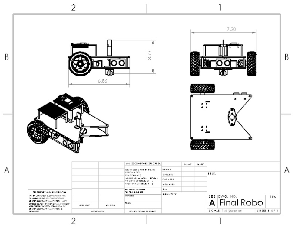
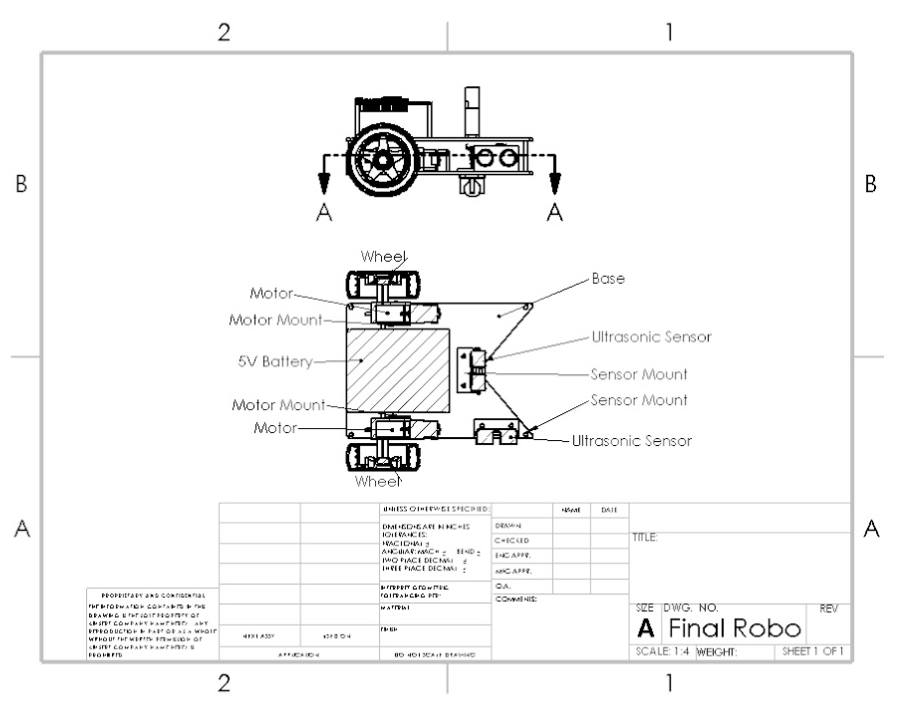
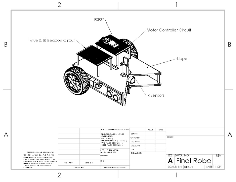
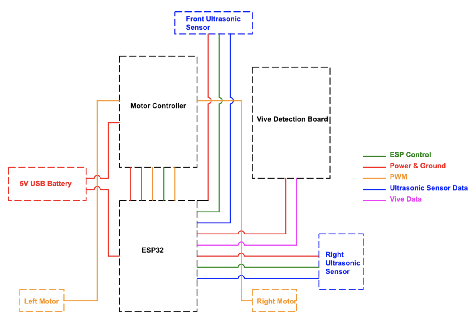
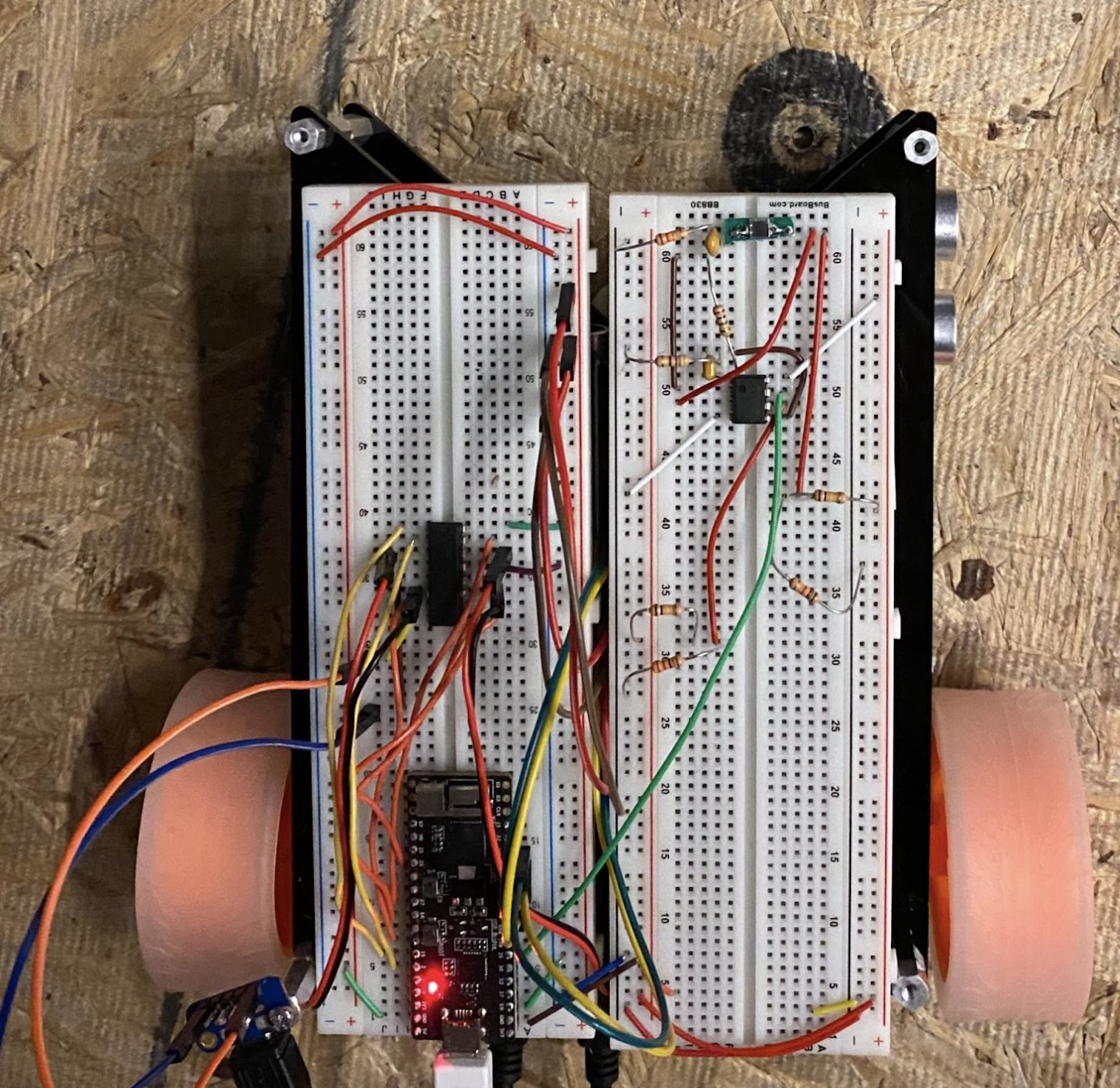
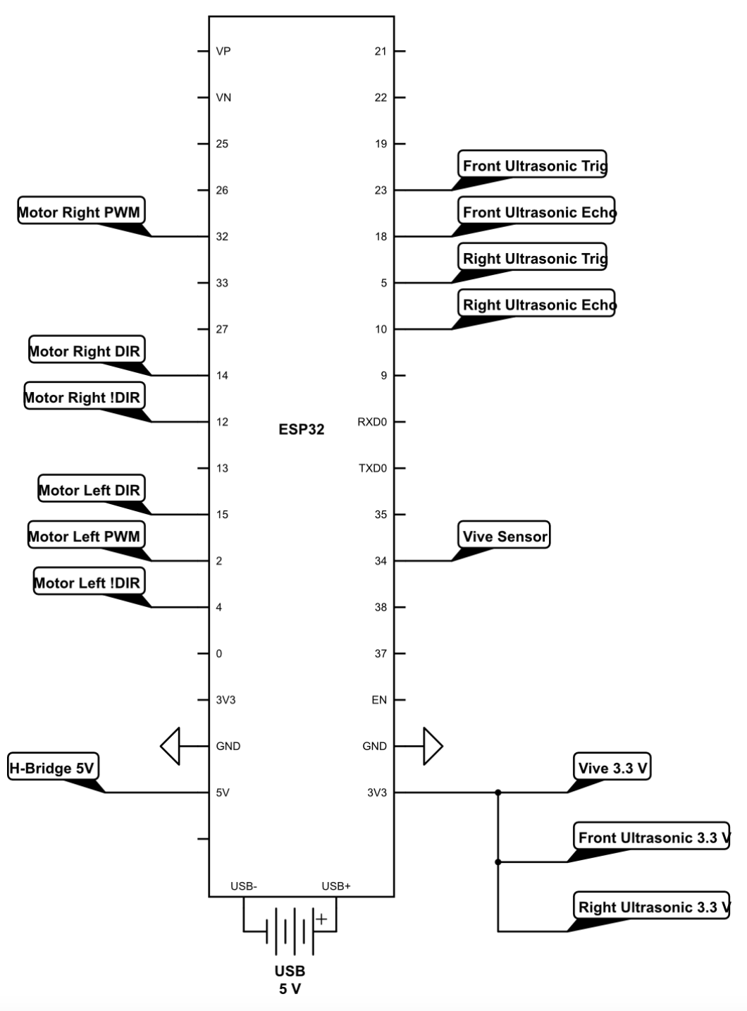
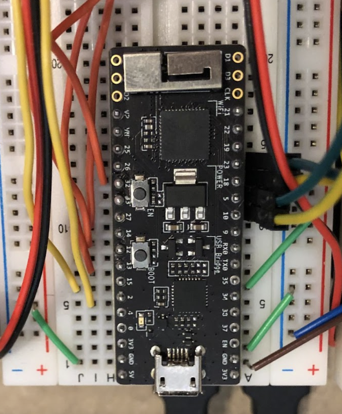
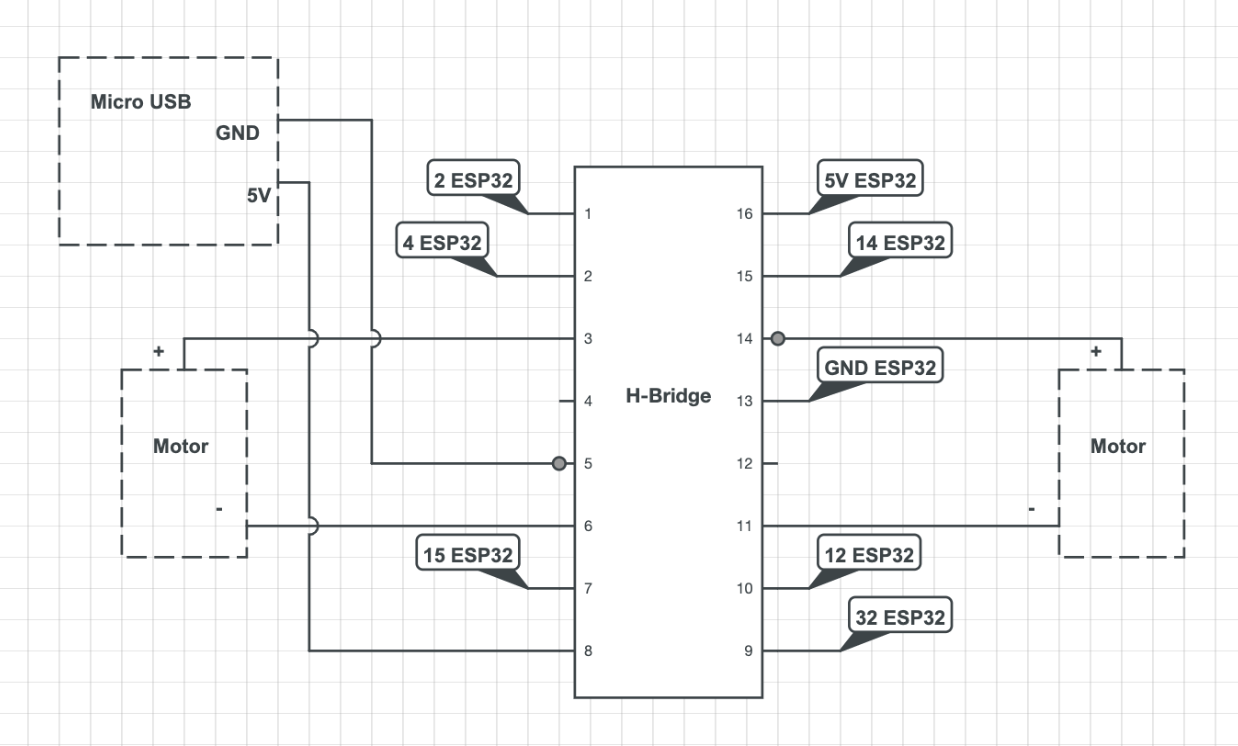
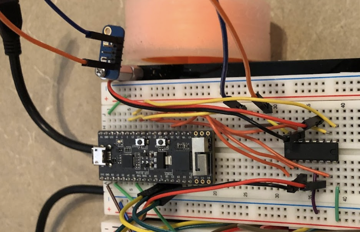
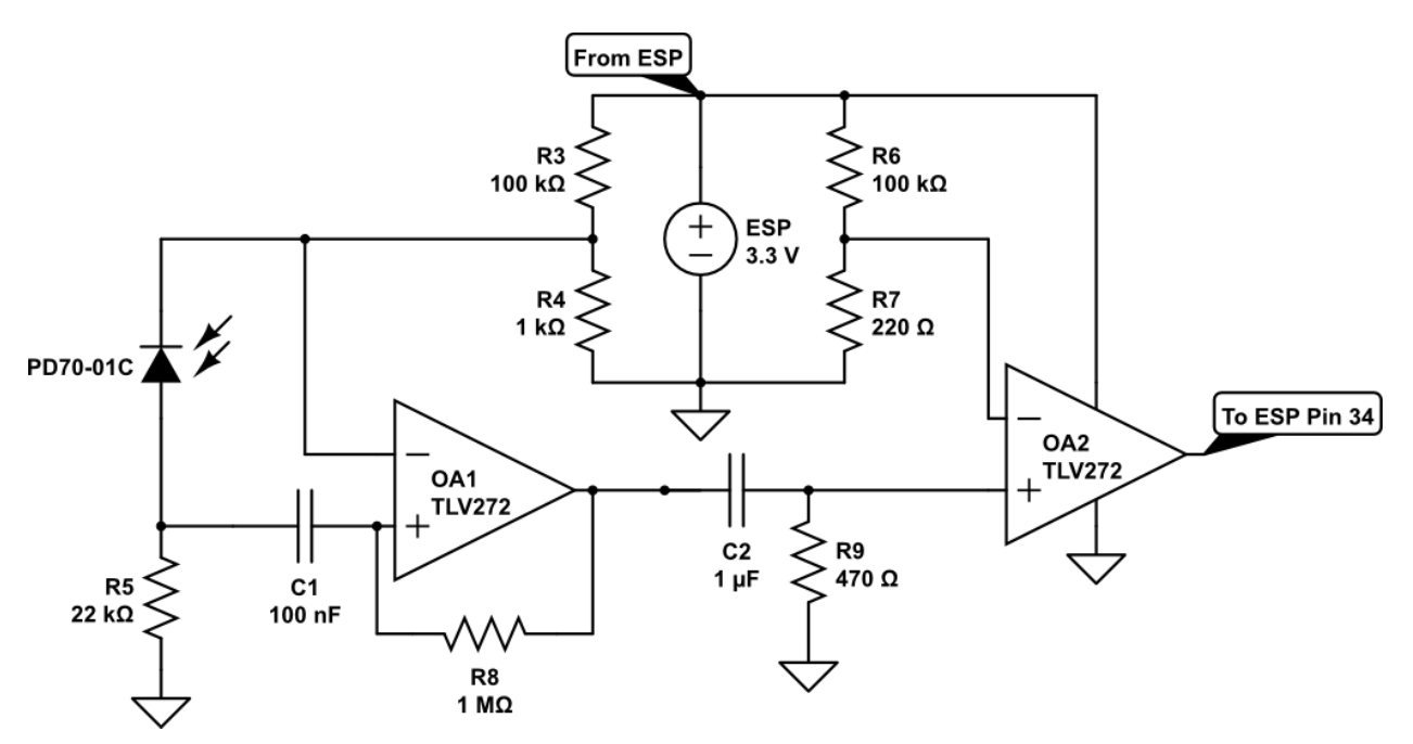
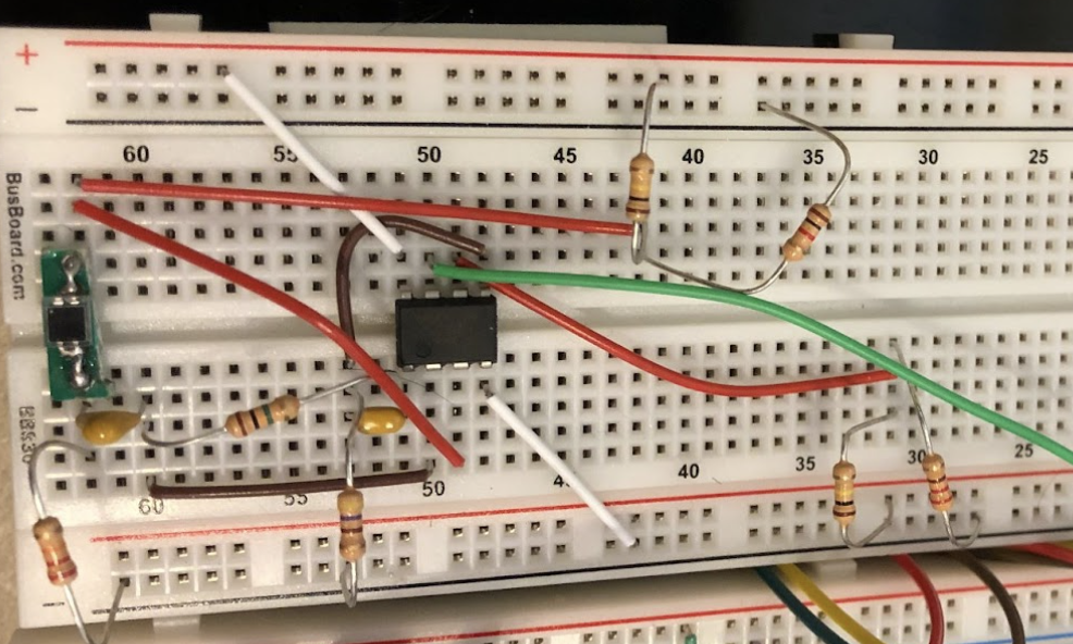
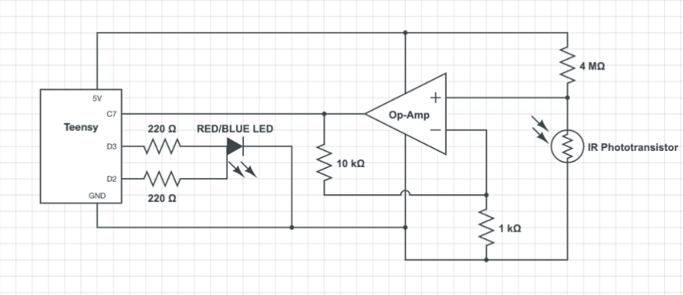
Our design achieves functionality through minimal complexity and weight, to optimize performance and ease debugging. Our frame is mostly rectangular with a concave V-shaped can collector up front, and includes two pieces of 1/8“ lasercut acrylic which enable electronic mounting. The minimalist mobile base uses a differential drive architecture with two motors and a singular, central caster at the front of the bot. Circuitry diagrams and pictures for each subsystem (namely the motors, Vive, IR Beacon, and central ESP32), as well as the overall system, are shown in the gallery below. Wiring design match the respective component spec sheets, with features ranging from resistors and capacitors to h-bridges and op-amps. Also shown below is the overall project BoM, the HTML webpage titled “Lightning McQueen,” and the mechanical drawings.
Task Completion via Hardware & Software
On the electrical side, a single ESP32 MCU controlled all other electrical features, integrating sensors and actuators via C++ code. The car achieved each of the following functions, using the methods outlined.
(1) Maintain power without outlet plugin
We used my Anker Powercore 1300 to simultaneously power the ESP32 and the two motors, using 1 USB each. The motors received power through a mediating H-bridge via a Micro-USB circuitboard adaptor
(2) Accept manual steering controls remotely
Our ESP32 maintained stable WiFi connection with my nearby laptop, accepting steering commands from its HTML webpage UI.
(3) Perform wall-following autonomously, circling around a square track
We mounted on two Ultrasonic distance sensors, and implemented feedback control to maintain a fixed distance from the right wall, as well as turn CCW whenever approaching front collision.
(4) Identify and move towards (either 23Hz or 700Hz) IR beacon
We build a separate circuit for beacon detection, featuring two phototransistors (IR sensors) and various resistors and Op-Amps. These features parse through atmospheric noise using high and low pass filters, isolating just the desired frequency beacon. Furthermore the two IR sensors are separated by a planar forward-facing barrier, indicating that the car should rotate until both sensors simultaneously detect the beacon, meaning it must be straight-ahead. To account for error we reran this pipeline at each discrete time step, until successful convergence.
(5) Transmit X-Y location via broadcast UDP
We used a Vive photodiode to obtain (X,Y) location readings from the provided Vive lighthouse, and sent them to an ESP32, before finally sending them to the HTML webpage through WiFi connection.
(6) Autonomously move to arbitrary X-Y location
We first sent the (X,Y) location readings from (5) to the ESP32 for some post-processing and noise cancellation. We then used geometry and trigonometry to calculate the target location in the car frame, and steer accordingly. To account for error we reran this pipeline at each discrete time step, until successful convergence.
